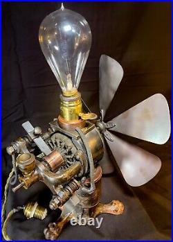
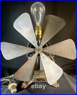
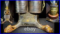

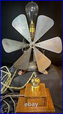
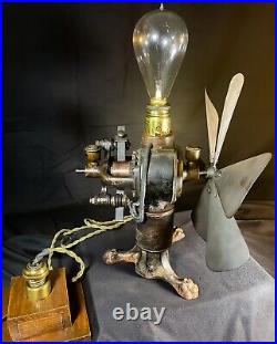
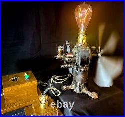
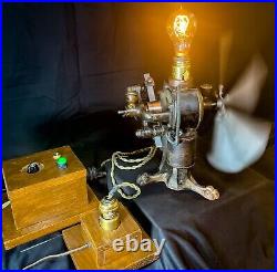
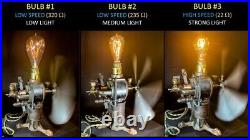
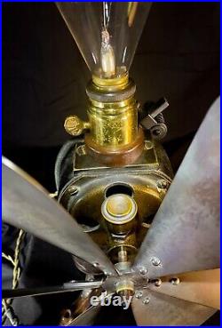
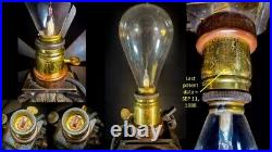
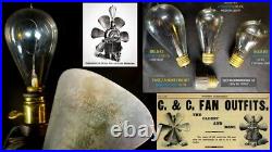
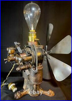
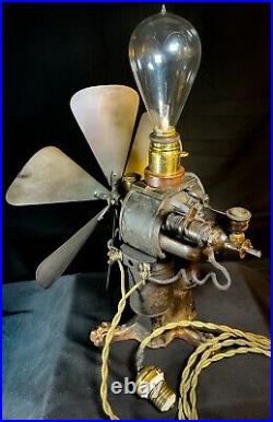
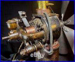
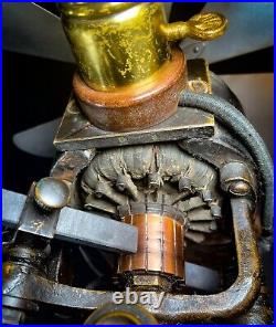
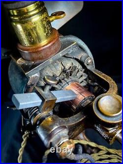
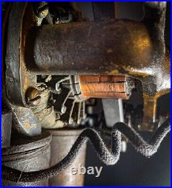
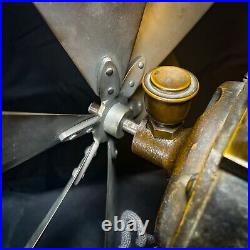
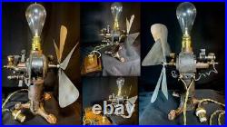
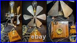
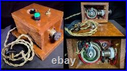
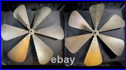
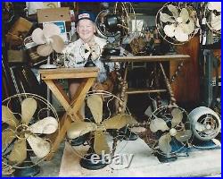

Loyd Davis, was an avid antique electric fan collector until his passing in 2011. The plan is to list 5-7 fans every week for sale. Buyers within the continental U. BUYERS FROM OUTSIDE THE CONTINENTAL U. I hope that everyone can get a fan that they will enjoy as much as my dad did! An AMAZING and SUPER RARE Curtis & Crocker (C&C) 12 6BB Type 1N Lamp Resistance Fan Outfit ca. 1890 that is an excellent and historically important example which would be an INCREDIBLE addition to any early electric fan collection. This is a “Top 5″ fan from the JLD 30+ year antique fan collection and absolutely his oldest son’s personal favorite. Because it has so many unique features that together tell a GREAT STORY of the very early days of how creative engineers, inventors, and scientists were beginning to harness the power of electricity and transform it into something for everyday use. Some of the unique features on this super rare C&C are. So glad you asked! A “fan outfit” was the combination of a fan blade + an electrical motor that was originally designed by early electrical motor manufacturers like C&C for industrial / commercial use. So the motor was “outfit” or “fit out” with a blade slapped on the front shaft of an early electrical motor. Powerful 110V DC Bipolar Motor : The 110V DC bipolar motor was designed and then patented by C&C in 1886 two years before Nikola Tesla first patented his AC induction motor in 1888. Consequently, only high-voltage DC power was available for commercial / industrial use when C&C combined their original motor design with a fan blade to create their fan outfit. The earliest C&C fan models did NOT have lamp resistance, i. E the light socket + incandescent bulb that was placed on top of the motor housing. However, C&C quickly realized that their original 110V DC motor was too powerful for a fan that would have wider appeal for use by non-industrial customers. So rather than change the basic design and manufacturing of their patented DC motor, they instead decided to come up with variations of their motor design that would be better suited for use as an electrical fan. And one of these variations was to add lamp resistance in permanent series with the two field coils to reduce the current supplied to the motor and thereby reduce power and rotational speed of the motor’s shaft and fan blade. And maybe the addition of the lamp/bulb helped them market this fan to wealthy residential customers as a dual-use appliance! Consumer product safety wasn’t a concern in 1890! So w/o a cage there was nothing to protect the owner from the high-speed blades! According to an article published in 1901 in Electrical Review Vol. 6 concerning the history of the development of the electric fan motor it stated: One of the early improvements.. Was the fan-guard, consisting of a brass wire cage around the fan… To protect anything such as a head or hand from mutilation, but as a matter of fact, it seems to owe its origin to a desire to prevent the fan or parts of it from coming out. Before the fan-guard was used several accidents occurred through blades coming off. On one occasion a plate-glass mirror was wrecked in Chicago, and on another a peaceful citizen, eating his lunch, had a neat groove cut in his scalp! So w/o a fan guard (aka cage) the adoption of the lamp resistance to lower the fan speed on this C&C fan outfit was an early, pre-cage, attempt to provide some protection to the owner. External Power Connection : The two power connections for the 110V DC supply are attached on the right side of the motor just above one of the two field coils. These two connectors and the two additional external connectors on the back of the motor that connect to the brushes are dangerous and could even be lethal. This is NOT a fan we recommend for every day use for this and other reasons noted above. Screw-In Plug for the Power Cord : The only electrical outlets in businesses and a few wealthy homes in major cities in 1890 were for electrical lighting. There were no traditional two-prong electrical outlets because there were no other electrical products / appliances for residential use in 1890 besides electrical DC lighting. So a screw-in plug was needed on the power cord to connect the motor/fan outfit to the available DC power supply used for incandescent DC lighting at that time. Victorian “Pawfoot” Design : The three cast iron lion paw feet on this base of the motor are a very traditional Victorian-era design that you don’t see on most fans that followed this very early C&C fan outfit. In only a few years time other electrical fans adopted a more “modern” (for that time) tripod or circular base with different design embellishments. Fully Exposed Commutator, Brushes, and Bipolar Field Coils : The brass commutator and brushes on the back of the bipolar motor and the two large and prominent field coils are fully exposed on this C&C fan. And this was the typical of most industrial DC motor designs of that time. But it would be very easy for something to accidently get caught in the rapidly spinning commutator, and the power connections to the external brushes were also a hazard. So exposed commutator’s like this fell out of favor in later fan designs where the commutator was completely enclosed in the motor housing along with the brushes and field coils. Just a few years later Edison designed, built, and marketed a low power 3V DC bipolar motor where the bipolar field coils, commutator, and motor windings were completely enclosed in his 1893 Model “Iron Clad” fan! C&C FAN OUTFIT DESCRIPTION. The 6-wing brass blade is a precise replica that was meticulously crafted. For my dad by Alan Willms more than 20 years ago. With all the details of the original blade. Alan has restored several C&C fans and many other early fans for AFCA members and his work is nothing short of outstanding. The field coils and motor windings are in EXCELLENT ORIGINAL CONDITION with no apparent damage anywhere. Field coils (3″ tall, 2.5″ diameter each) are positioned on top of a heavy cast iron base with three lion paws extending out from the fan to provide stability. The original cast brass motor tag positioned between two of the paw feet on the front of the fan has a patent date of Dec. 21, 1886 and indicates that the Type 1N motor (w/ serial # 6866) was designed to operate at 1500 rpm with a 110V DC supply. The motor itself is positioned on top of the field coils and the back of the motor is open so that the commutator and armature windings are visible. The insulating pieces made of mica? Between the brass bars on the fully-exposed commutator and the end cap were getting worn even though the fan was operational when we first tested it in 2019. So we replaced these with 3D printed parts made from Nylon which is very strong, flexible, resistant to abrasion, and has a melt point of 370° F. The commutator was then carefully shaved on a lathe to smooth out some grooves that were present to provide better contact with two new carbon brushes. As noted above a unique feature of this very early ca. 1890 “lamp resistance” fan was the use of an incandescent lamp i. Light bulb inserted into a Bergmann and Co. (New York) light socket affixed to the top of the motor. The very early last patent date Sept. 11, 1888 Bergmann light socket on this fan features a brass key, a brass shell with hard rubber top, and a “tongue in groove” switch that supplies direct current to both the bulb and the fan motor when the brass key is turned to the right. When turned on the additional resistance provided by the bulb in series with the two field coils reduces the current supplied to the motor and thereby reduced the fan’s rotational speed. Further, back in 1890 the speed of the motor/fan outfit could be changed by using bulbs with different resistance values where greater resistance decreases the motor’s direct supply current and fan speed. Consequently, three antique bulbs with different resistance values and light intensity are included with this C&C fan as shown in the photos. An antique fuse (short circuit) plug is also included for operation of the fan w/o the antique bulbs at lower DC voltages if desired. Two homemade oak boxes for operating the C&C fan are also included (see photos). The small box has an antique light socket with brass shell for receiving the male screw-in plug on the power cord that attaches to the fan’s external power connectors on the right side of the motor. This is how the fan would have been “plugged in” back in 1890 since this was before two-prong electrical plugs were in use. The small oak box has a power cord with an antique combination two-prong + screw-in plug that connects to another antique socket in the larger oak box. The large oak box then has a power cord for connecting to a standard 120V AC outlet. Variable DC output voltage. This setup then allows the 110V DC motor/fan to be operated at variable speeds with. All three antique light bulbs and the fuse plug. See video in this listing for one example of this. Both boxes are each mounted to their own oak base plate with a single antique hinge that provides easy access to the hardware in each box. In addition, there is sufficient space in the small oak box to add a bridge rectifier between the power cord and the antique light socket so that the fan could be operated directly, i. W/o the variable DC supply from the larger oak box, at full power by plugging the small oak box’s power cord directly into a standard AC outlet. All power cords, plugs, and sockets on the fan/motor and both oak boxes are antique. Additional videos beyond the one in this listing of this C&C fan are provided on the JLD. Fanman you tube channel. These videos demonstrate the variable speed operation of the fan with two different antique light bulbs (one low speed w/ low light intensity and one high speed w/ high light intensity) as well as the antique fuse. This listing is for 1 fan only. The last photo is meant to honor my dad as it shows him enjoying a handful of his antique fans. If you have any specific questions about this fan that I haven’t covered in this listing or are not clear in the photos, please feel free to ask, and I will do my best to answer them.
